Autoquip XLR AIR Manuale Utente
Navigare online o scaricare Manuale Utente per Apparecchiature Autoquip XLR AIR. Autoquip XLR AIR User Manual Manuale Utente
- Pagina / 36
- Indice
- RISOLUZIONE PROBLEMI
- SEGNALIBRI
Valutato. / 5. Basato su recensioni clienti
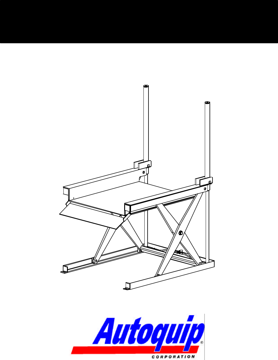
LOW REACH PAN LIFT
Model XLR
P.O. Box 1058 • 1058 West Industrial Avenue • Guthrie, OK 73044-1058 • 405-282-5200 •
FAX: 405-282-8105 • www.autoquip.com
830XLR Version 1.0
06/2003
INSTALLATION, OPERATION
AND SERVICE MANUAL
- LOW REACH PAN LIFT 1
- Model XLR 1
- INSTALLATION, OPERATION 1
- AND SERVICE MANUAL 1
- TABLE OF CONTENTS 2
- IDENTIFICATION & INS 3
- SAFETY SIGNAL WORDS 4
- SAFETY PRACTICES 5
- PRACTICES 7
- LABEL IDENTIFICATION 10
- SPECIFICATIONS 11
- LIFT BLOCKING INSTRUCTIONS 13
- INSTALLATION INSTRUC 16
- INSTALLATION INSTRUCTIONS 17
- OPERATING INSTRUCTIONS 18
- ROUTINE MAINTENANCE 19
- GENERAL MAINTENANCE 21
- DETAIL A 22
- GENERAL MAINTE 24
- ELECTRICAL SCHEMATIC 28
- REPLACEMENT PARTS LIST 32
- TROUBLESHOOTING ANAL 33
Sommario
Pagina 1 - AND SERVICE MANUAL
LOW REACH PAN LIFT Model XLR P.O. Box 1058 • 1058 West Industrial Avenue • Guthrie, OK 73044-1058 • 405-282-5200 • FAX: 405-282-8105
Pagina 2 - TABLE OF CONTENTS
10 Figure 5 Label 36400661 Figure 6 Label 36401594 LABEL IDENTIFICATION
Pagina 3 - IDENTIFICATION & INS
11 Model Travel (in.) Lifting Capacity (lbs.) Lowered Ht. (in.) Side Reach-Over (in.) Platform Size (in.) Base Size (in.) Edge Load
Pagina 4 - SAFETY SIGNAL WORDS
12 PUMP PRESSURE This lift incorporates a positive displacement pump machined to a high degree of accuracy and specially adapted to requirement
Pagina 5 - SAFETY PRACTICES
13 WARNING ! Only authorized personnel should perform inspection or maintenance and service procedures. Unauthorized personnel attempting thes
Pagina 6
14 FLIP-OVER MAINTENANCE LOCKS SHOWN IN PLACE ONBOTH SIDES OF BASE FRAME. Figure 7 Maintenance Locks LIFT BLOCKING INSTRUCT
Pagina 7 - PRACTICES
15 DANGER ! If for any reason you are unable to lower the lift completely onto the maintenance device(s), stop immediately and consult the fact
Pagina 8
16 1. Make sure installation area is clean before starting. 2. If the permanent electrical work is not complete, some means of temporary lines wi
Pagina 9
17 CLEAN UP 1. Clean up any debris from the area. A clean installation makes a good impression and creates a much safer environment! 2. To
Pagina 10 - LABEL IDENTIFICATION
18 1. Scissors lifts have maximum lifting capacity ratings (See the “Specifications” section). The safety relief valve has been factory set to o
Pagina 11 - SPECIFICATIONS
19 Normally scissors lifts will require very little maintenance. However, a routine maintenance program could prevent costly replacement of part
Pagina 12
2 Identification and Inspection 3 Safety Signal Words 4 Safety Practices 5 Label Iden
Pagina 13 - LIFT BLOCKING INSTRUCTIONS
20 Oil Viscosity Recommendations Environment (Ambient Temperatures) Recommended Oil Indoor location, variable temperatures (30 - 100° F) 10W3
Pagina 14
21 CYLINDER REPLACEMENT 1. Set the lift in the maintenance position (See LIFT BLOCKING INSTRUCTIONS on page 13.) 2. Unbolt the two hex head b
Pagina 15
22 Figure 8 Ram Detail GENERAL MAINTENANCE ROD END STOP(4) ROD BUSHINGS1/4" NPT PORTAIR BLEED
Pagina 16 - INSTALLATION INSTRUC
23 VELOCITY FUSE REPLACEMENT DANGER! Do not attempt to remove the velocity fuse until the lift is securely supported with the maintenance lock
Pagina 17 - INSTALLATION INSTRUCTIONS
24 Figure 9 Hydraulic Schematic GENERAL MAINTENANCE
Pagina 18 - OPERATING INSTRUCTIONS
25 WIRING AUTOQUIP "SUPER TORQUE' MOTORS Because Autoquip "Super-Torque" motors actually deliver substantially more horsepo
Pagina 19 - ROUTINE MAINTENANCE
26 (WHITE)(BLACK)(RED) (ORANGE)24V.L3L1L2L1L23/4 HORSEPOWERMOTOR:115 VOLT1 PHASE60 CYCLE(BY OTHERS)60 CYCLE115 VOLT1 PHASEO.L.T2T3T1L2L1L1L2DN. SOL
Pagina 20
27 24V.L3L1L2L1L23/4 HORSEPOWERMOTOR:230 VOLT1 PHASE60 CYCLE(BY OTHERS)60 CYCLE230 VOLT1 PHASEO.L.T2T3T1L2L1L1L2DN. SOL.ELECTRICAL SCHEMATICIDENTIF
Pagina 21 - GENERAL MAINTENANCE
28 115VAC-(RED)(A1)CONTACTOR24VAC-(BLACK)(WHEN USED)ELECTRICAL SCHEMATICLOCATED ON INSIDE OF FRONT COVER.TRANSFORMER PRIMARY CONNECTION DIAGRAMS ARE
Pagina 22 - DETAIL A
29 Figure 13 Guarded Footswitch Assembly GENERAL MAINTENANCE
Pagina 23
3 IDENTIFICATION When ordering parts or requesting information or service on this lift, PLEASE REFER TO THE MODEL AND SERIAL NUMBER. This inf
Pagina 24 - GENERAL MAINTE
30 Figure 14 Pushbutton Assembly GENERAL MAINTENANCE
Pagina 25
31 Figure 15 Limit Switch Wiring Diagram GENERAL MAINTENANCE
Pagina 26
32 PART # DESCRIPTION 20001137 Tongue & Groove Coupling 20022877 18DU16 Bushing 20023925 24DU16 Bushing 24002008 Washer, 1-1/8” x 1/64” T
Pagina 27
33 DANGER! To avoid personal injury, NEVER go under the lift platform until the load is removed and the scissors mechanism is securely blocke
Pagina 28 - ELECTRICAL SCHEMATIC
34 PROBLEM POSSIBLE CAUSE AND SOLUTION Lift does not raise. • The motor rotation for a 3-phase motor may be reversed. Reverse only two motor el
Pagina 29
35 PROBLEM POSSIBLE CAUSE AND SOLUTION Lift won’t lower. • The solenoid coil may be incorrectly wired, burned out, not rated for the voltage, or
Pagina 30
36 PROBLEM POSSIBLE CAUSE AND SOLUTION Lift seems bouncy during operation. • Lower the lift to collapsed position and continue to hold “DOWN” but
Pagina 31
4 SAFETY ALERTS (Required Reading!) The following SAFETY ALERTS are intended to create awareness of owners, operators, and maintenance personne
Pagina 32 - REPLACEMENT PARTS LIST
5 Read and understand this manual and all labels prior to operating or servicing the lift. All labels are provided in accordance with ANSI Z535.4.
Pagina 33 - TROUBLESHOOTING ANAL
6 DANGER! Extending the platform length or width beyond the factory limit could cause the unit to tip, which could result in personal injury
Pagina 34
7 CAUTION! Never run the pump for more than a couple of seconds without pumping oil. This applies to low oil conditions, improper motor rotati
Pagina 35
8 Figure 1 Label Placement Diagram XLR Item No. Qty Description Part No. 1 2 Caution – Familiarize Yourself With Op
Pagina 36
9 Note: Labels shown here are not actual size. Figure 2 Label 36401487 CUT LINE Figure 3 Label 36430050M Fig
Prodotti e manuali riguardandi Apparecchiature Autoquip XLR AIR
 (41 pagine)
© 2020, manymanuals.it. Tutti i diritti riservati | 0.057 s |
 Manymanuals.com
 Manymanuals.de
 Manymanuals.fr
 Manymanuals.it
 Manymanuals.pl
 Manymanuals.cz
 Manymanuals.es
 Manymanuals-pt.com
Commenti su questo manuale